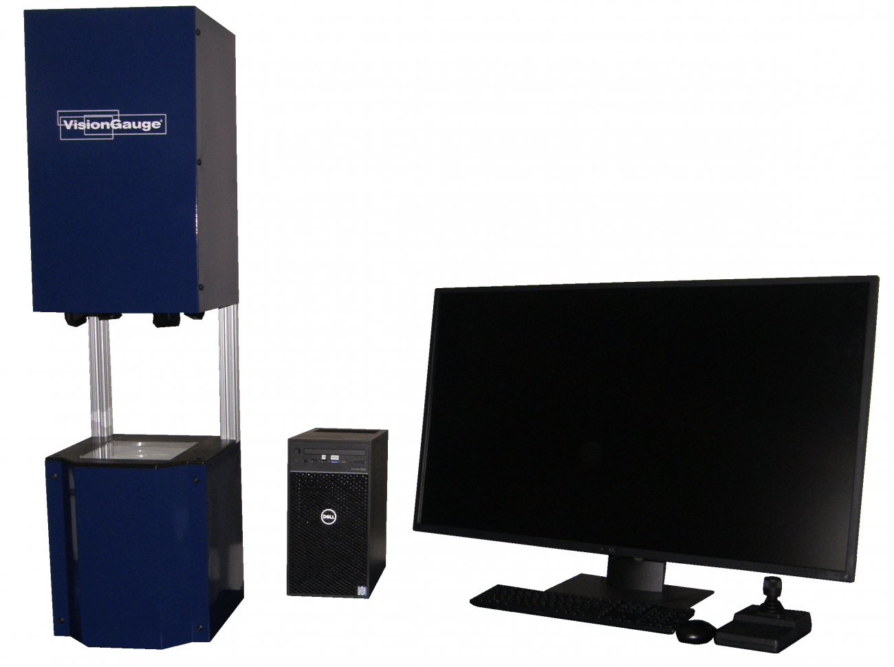
300 Series
The 300-Series VisionGauge® Digital Optical Comparator Field-of-View Systems are extremely cost-effective systems that are ideal for smaller parts (up to 1.7″ x 1.2″). Needs no overlays, templates or Mylars™ and can check multiple parts regardless of their orientation.
They have an extended depth-of-field for tall parts (as high as 1.1″) and a long working distance that provides ample clearance and room to work between the part and the lens.
They produce a stunning super-high-resolution image to carry out fine, detailed inspections.
Three different types of LED illumination are standard: collimated back, front off-axis (i.e. “dark field”) and front on-axis (i.e. “bright field”). This allows the system to produce crisp, sharp edges and perform beautifully even when working with hard-to-image materials (for example: shiny, reflective or even translucent surfaces) and difficult geometries (such as deep holes).
VisionGauge® Digital Optical Comparators are complete, ready-to-run Windows-based solutions. They are delivered network-ready and include on-site installation, NIST-traceable calibration & training.
The 300 Series Field-of-View Systems are desktop instruments that have all of the functionality of the 500 Series VisionGauge® Digital Optical Comparators, with the sole exception that they are limited to smaller parts.

Product Details
Features & Benefits
- Automatically compare parts to their CAD data with our proprietary CAD Auto-Align™ and CAD Auto Pass/Fail™ tools, in seconds
- Instantly computes and displays deviations-from-nominal and out-of-tolerance areas
- No operator-to-operator variation
- Extremely fast & easy-to-use!
- Needs no overlays, templates or Mylars™
- Full automated measurement capability
- The best, highest-resolution, clearest & sharpest image available!
- Joystick & barcode reader driven
- Intuitive software interface
- Innovative patent pending technology
- Accurate to +/- 0.0001″ (2.5 μ)
- Automatic image & data collection
- Built-in SPC capability
- All-LED computer-controlled multi-illumination modules (back, front square-on and front oblique) are standard!
- High-resolution precision optics
- No moving parts
- No consumable parts
- Convenient desktop configuration
- Easy to learn and operate. You’ll be up & running on “day one”.
- Perfect for both the shop floor and the quality control lab
Technical Data
- Model
- VG300DOC-30V-40X/ VG300DOC-30V-20X/ VG300DOC-30V-10X:
- Maximum part size (i.e. field-of-view dimensions)
- 0.85" (h) x 0.60" (v) (i.e. 1.0" diagonal) / 1.7" (h) x 1.2" (v) (i.e. 2.0" diagonal) / 3.1" (h) x 2.3" (v) (i.e. 3.9" diagonal)
- Maximum part height
- 0.2"/ 0.8"/ 3.0"
- Vertical clearance (between the working surface and the lens)
- 4.1"/ 6.5"/ 8.9"
- Equivalent optical magnification (approx.)
- 40X/ 20X/ 10X
- “Desktop" configuration
- Yes
- Image viewing area (diagonal)
- 38"
- Software
- VisionGauge® OnLine Standard Edition
- Software interface
- Intuitive, windows-based graphical user interface (i.e. “point & click”)
- Part fixturing configuration (if desired)
- Tapped hole pattern on main working surface (#10-24)
- Working surface finish
- Hard coat anodized aluminum with glass insert
- Maximum load
- 50 lbs
- Camera
- High-resolution, digital (9 MegaPixel)
- Live video “refresh”
- Real-time
- Illumination
- LED-based (for very stable illumination conditions, with a very long life) • Programmable and computer-controlled (for repeatable illumination conditions) • Includes 3 different illumination modules: collimated transmitted (i.e. back), on-axis reflected (i.e. front) and oblique reflected (i.e. front) illumination modules are standard
- Lens
- Very low distortion telecentric, with long working distance and extended depth-of-field
- Real-time mathematical image processing, enhancement and correction
- Yes
- Multi-monitor display
- Yes
- Overall Quad-Monitor size
- 35" (wide) x 27" (high)
- Auto Pass / Fail (to determine if the part matches the CAD data)
- Yes
- Auto Pass / Fail Control Sections & Geometric ENTITIES
- User-selectable, with bi-directional tolerances
- CAD Auto-Align
- Yes: automatically align the CAD data to the part (either XY or XY & Rotation alignment) along an arbitrary number of user-specified datums.
- Extended set of high-accuracy measurement tools
- Yes
- Sub-pixel accurate edge detection
- Yes
- Quickly carry out on-screen measurements using either the mouse or joystick
- Yes
- Joystick
- 3-axis, 3-speed industrial grade
- Image annotation tools
- Yes
- Quickly and easily save images of parts, either with or without the CAD overlay, measurements as well as time & date information
- Yes
- Built-in SPC capabilities, with automatic numerical charts & PASS / FAIL graphs
- Yes
- Automatic data export to Excel™
- Yes
- Automatic data export to other applications
- Yes (through Windows™ DDE or other mechanisms)
- Built-in Dynamic Data Exchange (DDE) support
- Yes
- Easy file data import & export
- Yes
- Automatically load-in a CAD file using the system’s barcode reader
- Yes
- Barcode reader
- Honeywell, industrial grade
- Align the DXF overlay (position & orientation) using either the external 3-speed joystick or the intuitive on-screen controls
- Yes
- DXF Overlay Toolbox for quick CAD data and settings changeover & recall
- Yes (“1-click”)
- Quick changeover between DXF overlay and crosshair or bull’s eye (for measurements)
- Yes (“1-click”)
- Supervisor-level / operator-level password protection
- Yes
- Operating System
- Windows™ 7
- Built-in “F1 Help”
- Yes
- Power requirements
- 110V, 2 Amp
- Operating temperature
- 10 °C - 30 °C
- Clear and easy-to-use documentation (both printed and electronic “pdf” format)
- Yes
- Support (by phone, fax & email)
- Included for a full year
- Free software updates
- Included for a full year
- Warranty
- 1 year (complete)
Videos
Sorry, there are no videos for this machine.
